A. Assessment of wear and turning errors
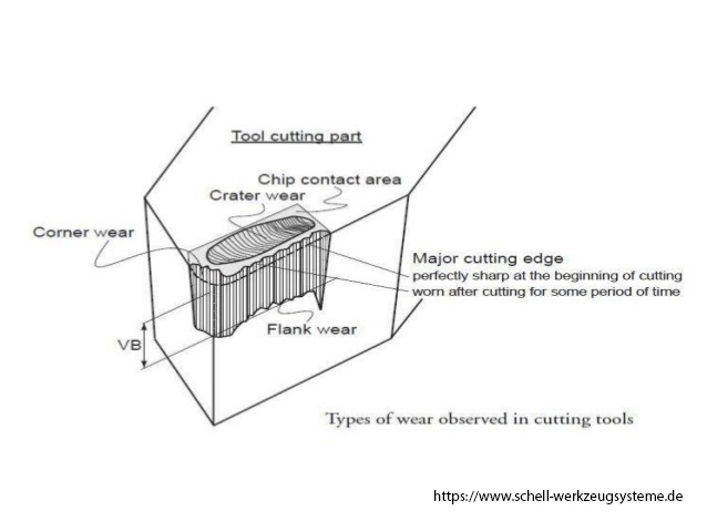
1. built-up edge
Too low a cutting speed or too low a tooth feed can lead to a built-up edge. If the rake angle is too small or the cutting edge bevel is not optimal, the chip flow can be improved by using a fluted insert or by a tool with a positive rake angle. If the cooling is not optimal, the chips "bake" at the contact surface. The cooling volume should be large enough to reach directly to the cutting edge and ensure sufficient heat dissipation. In some areas, the use of a different coating leads to improvements.
2. Crumbling of the cutting edge
Too low a cutting speed or too high a tooth feed favors the crumbling of the cutting edge. Increasing or decreasing the values often helps. u A tougher type of cutting material also counteracts the crumbling of the cutting edge. Due to the softer cut, an insert with a groove or the use of a tool with a positive rake angle can be useful. Too much cutting depth loads the cutting edge unnecessarily. Often, reducing the depth of cut while increasing the cutting speed gives better results.
3. Thermal cracking
Too high cutting speed and too high tooth feed burden the cutting excessively. If no improvement can be achieved by reducing the tooth feed, the following measures are still possible: By choosing a smaller setting angle, the position of the cutting plate to the workpiece is improved. u Comb cracks can also be caused by strong temperature changes at the cutting edge. Dry machining, as well as the adequate supply of cooling fluid can help.
4. notching
During notch wear, the chips "grind" material out of the cutting insert at the maximum chip depth. A reduction in cutting speed and tooth feed ensure better chip flow, as well as choosing a tougher grade of cutting material. u The choice of a reduced setting angle or a variation of the depth of cut counteract this. If the notch wear is caused by burr formation, a change in the working position of the milling cutter can bring improvement.
5. crater wear
Crater wear is a thermal problem. If coolant is not or only insufficiently brought to the cutting edge, it heats up too much. The same effect occurs even at too high a cutting speed or too high a feed rate. The choice of a more wear-resistant grade or another coating can counteract scoring wear.
6. Plate break / cutting edge breakage
The cause of a plate fracture or a cutting edge breakout is a mechanical overload of the cutting insert. The triggers for this can vary: u Incorrect installation of the cutting tip may result in an air gap, so that the contact surface of the cutting tip may be damaged
7. Cutting edge deformation
If the cutting temperature is too high and the cutting pressure too high, this can lead to a thermo-mechanical deformation of the cutting edge. Remedy provides the choice of a wear-resistant cutting plate and / or a significant improvement in cooling.
8. Flank wear
Excessive flank wear often results from too high cutting speed or too little feed. Adjust these values or choose a more wear-resistant grade.
9. burr
If the cutting edge is not or no longer sharp enough, this can lead to burr formation. A more positive geometry of the insert (eg with a groove) or the tool can help. u maybe. If only the direction of the cutting force is unfavorable, then an improvement of the setting angle can be achieved.
10. Adhesive chips
For very soft, "lubricating" base material, the use of a coated carbide grade, possibly with a sliding layer, leads to better drainage of the chips. In the case of suitable inserts, it is also possible to use coolant. Adhesive chips can also be counteracted by an increase in the tooth feed: The chips become thicker, can absorb more temperature and thus reduce the heating of the cutting plate.
11. Machine overload
If an overload of the machine occurs, the occurring cutting pressure is too high. The most common cause is the choice of a too large tool and / or a too large insert. Reduce them or choose a positive tool geometry. In order to reduce the cutting forces, the cutting speed, the tooth feed or the depth of cut can also be reduced.
12. recut
Re-cutting, which is indicated by disturbing grooves in the cut surface, can usually be eliminated by choosing a smaller tool diameter or a smaller setting angle, since all these measures reduce the cutting force. Often the change of the (worn) inserts leads to success.
13. Poor surface quality on the workpiece
If the cause is not the occurrence of vibrations, it should be checked whether there is a runout error and this can be eliminated by aligning the spindle, recording or tool. u For flat surfaces, it is recommended to use inserts with flat bevel instead of corner radius or even special face milling cutters. Or is simply the feed per revolution too high?
14. Chips do not flow away
The optimal drainage of the chips is the alpha and omega of machining. Take care of B. with plenty of air supply that already removed chips do not come again "under the cutter". Even in a too narrow chip chamber can lead to chip accumulation. Use a more split tool with fewer teeth. By reducing the cutting depth, cutting width or feed per tooth, the chips become smaller and can also flow better. In the case of "lubricating" materials, special coated cutting materials with a sliding layer or special cutting edge geometries (eg fillet) often provide a remedy.
15. vibrations
One possible cause is insufficient rigidity of the machine. If it is not possible to change to a more stable machine, the use of small tools should be considered. Especially for unstable machines small inserts are in the program. Also a reduction of the cutting speed and / or cutting depth can bring an improvement. If vibrations occur due to unstable recording combinations, it should be checked whether a shorter version is possible.
16. Workpiece outbreaks
Workpiece breakouts due to excessive cutting forces can be eliminated by selecting a sharper cutting edge or a more positive tool geometry. is also only the cutting force unfavorable to the workpiece; then a change in the Fräsbahnrichtung or the change from DC and reverse can bring an improvement. Especially with brittle materials can be prevented by chamfering the tool exit edge breaking out of material.
B. Troubleshooting drilling
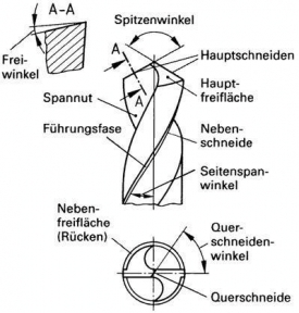
1. Splitting the drill
Game of the drill spindle in the axial direction. Springy clamping of the workpiece. Too much feed. Remedy: Eliminate dead gear in spindle. Firmly clamp workpiece. Reduce feed.
2. Breakage of the drill
Bad seat in the food. Insufficient removal of chips from the borehole. Drilled over the spout of the spiral in the material. Worn or badly ground drills. Remedy: Firmly clamp the drill. Frequent emptying of the grooves; take longer drills. Do not drive over the spout into the material. Timely and in accordance with regulations.
3. Drill hooks in and breaks
Porous sites in the material; oblique exit surface. Remedy: Lower feed. Clamp the workpiece well. Be careful when drilling by hand.
4. Chamfers rub off
Too high speed, poor cooling. Remedy: Reduce speed, add lubricant in sufficient quantity.
5. Drill gets dull quickly
Feed too big, bad cooling. Remedy: Grind drill sharply, reduce feed rate, supply sufficient coolant.
6. Drilling machine rears up, springs back on exit the drill, drill breaks
feed pressure too high, too weak machine. Remedy: Reduce the feed rate, do not load the machine higher than the design allows.
7. Breakage of thin drills
Drill protrudes too far out of the chuck. Remedy: If possible lead into drill bushes, otherwise tension drill to half length. Drill hole to half depth, drill drill so that it protrudes. Drill hole to the end.
8. Cylindrical drill shaft shows grooves
Drill was not clamped tight enough to slide. Drill overstressed due to excessive feed. Drill grooves blocked by chips, thus great friction. Remedy: Secure the drill firmly in the chuck and deep enough. Reduce feed. Clogged flutes often clean from the chips.
9. Flap is broken or damaged
Clamping cone was greasy or dirty or with burrs, so that the cone pulley had to transmit the entire torque. Damage can also be caused by violent loosening. Drilling out predrilled holes: the drill hooks in and loses contact with the Morse taper. Remedy: Clean the clamping cone before inserting grease and dirt. Burr must be eliminated. The release should be done only by hand with the wedge driver. Main cutting correction, i. reduce the rake angle. Polished to DIN 1412 B.
10. The drill tip shows tarnishing colors
The drill has been overheated due to excessive cutting speed or poor cooling. For deep holes, the feed was too large. Remedy: Reduce the cutting speed by reducing the speed. Ensure adequate cooling. Reduce feed for deep holes.
11. The bore is larger than the nominal diameter of the drill
The drill bit has been ground so that the cutting edges have different lengths. Remedy: Grind the drill correctly after teaching or better on special machines.
12. The hole shows ridge and burr formation
Drill was dull. Burr formation at the exit point can also occur during drilling without a base and at too great an advance during the drill penetration. Remedy: Use only sharpened drills and suitable documents. When drilling through the feed is to be reduced.
13. The drilling wall is very rough
Drill was blunt, feed too large or lubrication insufficient. Remedy: Grind the drill sharply, reduce the feed rate, supply a suitable lubricant in sufficient quantity.
14. The hole is wrong
Workpiece was skewed or misaligned because the documents were skewed or shavings under the workpiece, underlays or even under the vise. Remedy: Place work piece in vice on equal height parallel pieces or use straight paper. First clean chips from chips.
15. The hole is out of round, crooked and lost
It has been drilled with too high feed pressure; As a result, the drill has bent or the machine has been reared. Hole center and drill tip do not match. Drill has hit. Remedy: Reduce feed to reduce feed force. Align the workpiece exactly to the drill tip. Ensure proper running of the drill.
16. The drill is much quieter after removing the drill than when drilling
The drill beats or the workpiece has been inaccurately aligned with the drill tip during tapping. Remedy: Clamp the drill precisely and align the workpiece with the drill bit before drilling.
C. Troubleshooting threading
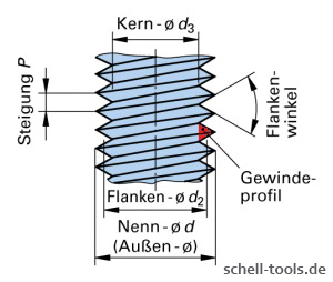
Thread produced is too small
- pitch error
- Too low tolerance position
- Too strong forced guidance
- Worn section has not been reground correctly
- Tap too small due to no. of regrinds
Thread comes to narrow in bottom area of the hole
- Work with rigid chuck holder or synchro tapping holder
- Use a tap with longer cutting edge(better leed-control)
Thread produced is too large
- Tap out of alignment with the hole or tap not running true
- Core hole too small
- Feed pressure incorrect producing thin or deformed threads
- Incorrect tap for the material eg. a) Cutting rake too great b) Incorrect thread relief c) Chamfer lead too short
- Incorrect sharpening eg. chamfer relief uneven or excessive Tap Cutting Edges Chip
- Cutting edge geometry (chamfer lead, rake-,chamfer-, spiral point angle) not retained
- Tap hitting bottom of a blind hole
- Material too hard or abrasive of the type of tap
- Tap reversed carelessly
- Lubrication lacking or of wrong quality
Bad thread surface
- Tap drill to small
- Chips clogging flutes
- Broken threads on taps
- Improper resharpening of tap
- Lack of lubricant or use of wrong type
Thread surface doesn't meet requirements
- Cutting edge geometry not suitable for the application
- Cutting speed too high
- Insufficient coolant (concentration and supply)
- Chip congestion
- Tapping size hole too small
- With tough, hard materials loading on tool too much or pitch too steep
- Built-up edge
- Cold welding
Short tap tool life / Excessive Tap Wear
- Hole work hardened
- Insufficient or incorrect lubricant.
- Material is abrasive or inclusions present. Surface treated tap required
- Tapping speed too high
- Wrong tap selection
Tap Breaking
- Drilled hole too shallow
- Hole work hardened
- Incorrect tapping drill size
- Incorrect fixture or Holding device
- Insufficient or Incorrect lubricant
- Work hardened material
- Misalignment of tap and hole
- Tapping speed too high
- Tap hits bottom of hole
Tap Breaking On Reversal
- Tap cutting too tightly. Cutting face angle should be increased
- Tap galling. Face angle on back of land should be increased
- Chips wedged between flutes
Material sticking at the flanks on the taps
- Cutting speed is not optimal
- Coolant/lubrication upgrading
- Use coated taps
D. Evaluation of Wear and Errors During Milling
[Translate to English:]
Schlechte Oberfläche beim Fräsen
- Härtere Hartmetall Sorte verwenden
- Schnittgeschwindigkeit erhöhen
- Vorschub verringern
- Schnitttiefe verringern
- Kühlschmierstoff-Verwendung prüfen
Ausbröckelung der Werkstückkante
- Vorschub verringern
- Schnitttiefe verringern
- Freiwinkel erhöhen
- Zähnezahl am Fräser erhöhen
- Fräser-Steifigkeit prüfen, Auskraglänge ändern
- Fräsmaschine mit höhere Leistung und Steifigkeit wählen
Nicht parallele oder ungleichmäßige Werkstück-Oberfläche
- Vorschub verringern
- Schnitttiefe verringern
- Freiwinkel erhöhen
- Zähnezahl am Fräser verringern
- Fräser-Steifigkeit prüfen, Auskraglänge ändern
- Fräsmaschine mit höhere Leistung und Steifigkeit wählen
Übersicht über Fehler und Ursachen beim Fräsen als PDF Datei herunterladen.
E. Assessment of wear on grinding wheels
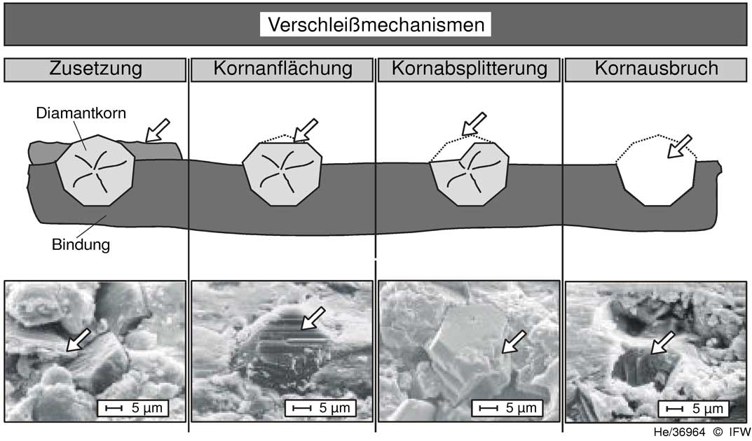
Zusetzen der Schleifscheibe
Zusetzungen (Verschleiß durch Auftragung) bezeichnet die Einlagerung von Werkstückpartikeln in den Spanraum der Schleifscheibe oder des Schleifstifts. Das Haften der Partikel im Schneidenraum wird auf mechanische Haltekräfte zurückgeführt, die durch Hinterschneidungen zwischen den unter hohem Druck in den Spanraum eingepressten Spänen und den rauen Kornoberflächen entstehen.
Anflächung der Schleifkorns
Kornanflächung bezeichnet das Abstumpfen von Schleifkörnern, welches als Folge von mechanischem Abrieb, Korrosion, Diffusion oder Adhäsion auftritt. Kornanflächungen führen zu reibungsbedingten höheren Schleifkräften bei geringerer Zerspanleistung. Dabei ist der makroskopische Verschleiß gering.
Absplitterung der Schleifkorns
Kornabsplitterungen entstehen aufgrund einer mechanischen und/oder thermischen Belastung der Schleifkörner beim Schleifen. Die Verschleißform kann sich als günstig erweisen, da neue und scharfe Schneidkanten erzeugt werden (Selbstschärfung) und gleichzeitig nur ein geringer makroskopischer Verschleiß auftritt. Zudem führen Kornsplitterungen zu niedrigen Schleifkräften. Beim Herstellungsprozess von Industriediamanten kann durch das Einbringen von Dotierungen das Splitterverhalten der Schleifkörner gezielt beeinflusst werden.
Ausbruch der Schleifkorns
Kornausbruch (Bindungsverschleiß) ist definiert als das Ausbrechen von Schleifkörnern oder Korngruppen bei mechanischer Überbeanspruchung bzw. bei thermischem oder chemischem Verschleiß des Bindungsmaterials. Kornausbruch führt zu einem hohen Volumen- und Profilverschleiß an der Schleifscheibe.
Quelle: Berichte aus dem IFW Band 08/2003, Herausgeber: Prof. Berend Denkena

